Preface
This tutorial was made solely for the purpose of education and it was designed for students taking Applied Math 0330. It is primarily for students who have very little experience or have never used Mathematica and programming before and would like to learn more of the basics for this computer algebra system. As a friendly reminder, don't forget to clear variables in use and/or the kernel. The Mathematica commands in this tutorial are all written in bold black font, while Mathematica output is in normal font.
Finally, you can copy and paste all commands into your Mathematica notebook, change the parameters, and run them because the tutorial is under the terms of the GNU General Public License (GPL). You, as the user, are free to use the scripts for your needs to learn the Mathematica program, and have the right to distribute this tutorial and refer to this tutorial as long as this tutorial is accredited appropriately. The tutorial accompanies the textbook Applied Differential Equations. The Primary Course by Vladimir Dobrushkin, CRC Press, 2015; http://www.crcpress.com/product/isbn/9781439851043
Return to computing page for the second course APMA0340
Return to Mathematica tutorial for the first course APMA0330
Return to Mathematica tutorial for the second course APMA0340
Return to the main page for the course APMA0330
Return to the main page for the course APMA0340
Glossary
Dyer Model

The following model was developed by the American engineer Stephen W. Dyer (born in 1966) originally from Ann Arbor, Michigan. He received B.S. (Brigham Young University), M.S., and Ph.D. (University of Michigan) degrees in Mechanical Engineering and an MBA from the University of Michigan’s Ross School of Business. He started his career in engineering research and development and led research efforts for advanced industrial and aerospace vibration control systems and holds numerous patents in this field. He has more than 20 years of industry and consulting experience in the automotive, industrial goods, and high tech sectors. Prior to his current position, he was a partner in the Shanghai office of management consultancy Bain & Company. Dr. Dyer currently leads Ford Motor Company strategic initiatives in Asia Pacific across both the core automotive business and emerging mobility initiatives.
Dyer's model of electromagnetic actuator.
Actuators (also called power transducers) convert a given kind of energy into mechanical energy. These electrical devices transform input energy (control variable) to output mechanical work (acting variable). There are different classes of actuators depending on the physical principle on which the energy conversion takes place. Some of these classes of actuators which are widely used in industrial applications include hydraulic actuators, electrostatic actuators, electromagnetic actuators, thermal expansion actuators, and pneumatic actuators.
An actuator that uses the electromagnetic principle for energy conversion is called an electromagnetic actuator. Control variable of this actuator is electric current and acting variable is force interaction and its effects. Electromagnetic actuators convert electrical and mechanical energy into one another. The energy conversion takes place in the so-called air gap which separates the stationary member (stater or fixed contact) and moving member (rotor or moving contact) of the actuator. These actuators produce force and torque by means of magnetic field. Magnetic fields have higher energy density compared with electrical fields that’s the reason for using magnetic fields in these sensors. The fundamental principles that govern electromagnetic actuators are Faraday’s laws of electromagnetic induction, Lorenz force of electromagnetic forces, and Biot-Savart law. Since the control variable of this kind of actuator is the electric current fed by the power converter drives, so these can be easily controllable.
The electromagnetic actuator consists of two basic parts---electric and magnetic circuits. The electric circuit is formed by a cylindrical coil wound fixed on the frame. The magnetic circuit is formed by the shell and movable core. Movable core is placed on the axis of the actuator and can move freely in it. To reduce the friction force between the moving core and shell as well as to prevent their mutual impact the core is placed in a nonmagnetic sliding tube. The current in the coil produces magnetic field that gives rise to the Maxwell force which acts on the ferromagnetic core.
We consider an electromagnetic actuator that moves in steps to counteract system's changes in inertia. Such actuator can be used to balance rotational machinery. The step-by-step engine represents a version of the synchronous jet engine. The most widespread synchronous engines of low power are in use where it is necessary to receive a constant speed, low material inputs, and simplicity of management. Structurally, synchronous jet engine consists of stater and rotor that are made of electrotechnical steel. On stater, there is a three-phase winding (probably single-phase execution). The rotor should have salient-pole. The step-by-step engine moves discretely on each impulse acting in stater winding, thus, transforming an electric impulse to an impulse of movement.
 |
 |
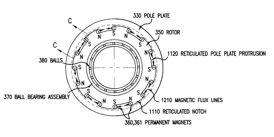
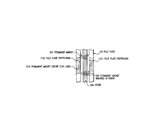
The driving force for each step is provided by current running through the system. There are multiple permanent magnets at various points of the periphery of the rotor. They have alternating polarity so they will form a magnetic circuit with the outer pole plate (as seen in Figure 2). This is part of a balancing device to compensate for mass unbalance.
The coil can be energized with a pulse of current coming from a power source. This creates an electromagnetic field that suppresses the magnetic field in one of the permanent magnets in a pair and enhances the magnetic field in the other one (because of their opposite polarity). As a result, the net effect is for the rotor to rotate toward the middle of the step in the path. Then the current turns off and the momentum of the magnets causes them to continue to move forward to a new resting position at a different angle. It will stay at this position until the coil receives more current. The cross section is seen in Figure 2 where there is a clear airspace that the magnetic field moves across to rotate the balancer.

The forces acting on the system is essentially a summation of the various torques that are in play.
The first torque is the restoring torque where the magnetic circuit will move the rotor to a resting equilibrium position at each step:
Using the rotational equivalent of Newton's second law (T = I α), we can compile the above equations in the following form, where T is equal to a sum of all the torques available, I is the rotational moment of inertia for the root, and α is the angular acceleration (or the second derivative with respect to time of angular position):
To graph the simulation, we use the following material coefficients:
With all the material coefficients applied to the differential equation, we get


Return to Mathematica page
Return to the main page (APMA0330)
Return to the Part 1 (Plotting)
Return to the Part 2 (First Order ODEs)
Return to the Part 3 (Numerical Methods)
Return to the Part 4 (Second and Higher Order ODEs)
Return to the Part 5 (Series and Recurrences)
Return to the Part 6 (Laplace Transform)